About this document
This Technical Note sets out how to test the durability of interconnects and interfaces in copper-filled through-glass vias with double-sided wiring. It centers on IST and solder float and also covers reflow, thermal cycling, temperature-humidity testing and failure analysis.
Download
An English edition is not available yet. The Korean document is below.
Summary
Glass via reliability is decided at the via-to-wiring connections and the glass–copper interface. The note covers test conditions, pass criteria, cross-section analysis and a PDA interface comparison plan, centered on IST, which tracks resistance while repeatedly heating a daisy-chain coupon with current and cooling it, and solder float, which briefly contacts the coupon with a 288 °C solder surface.
Conclusion
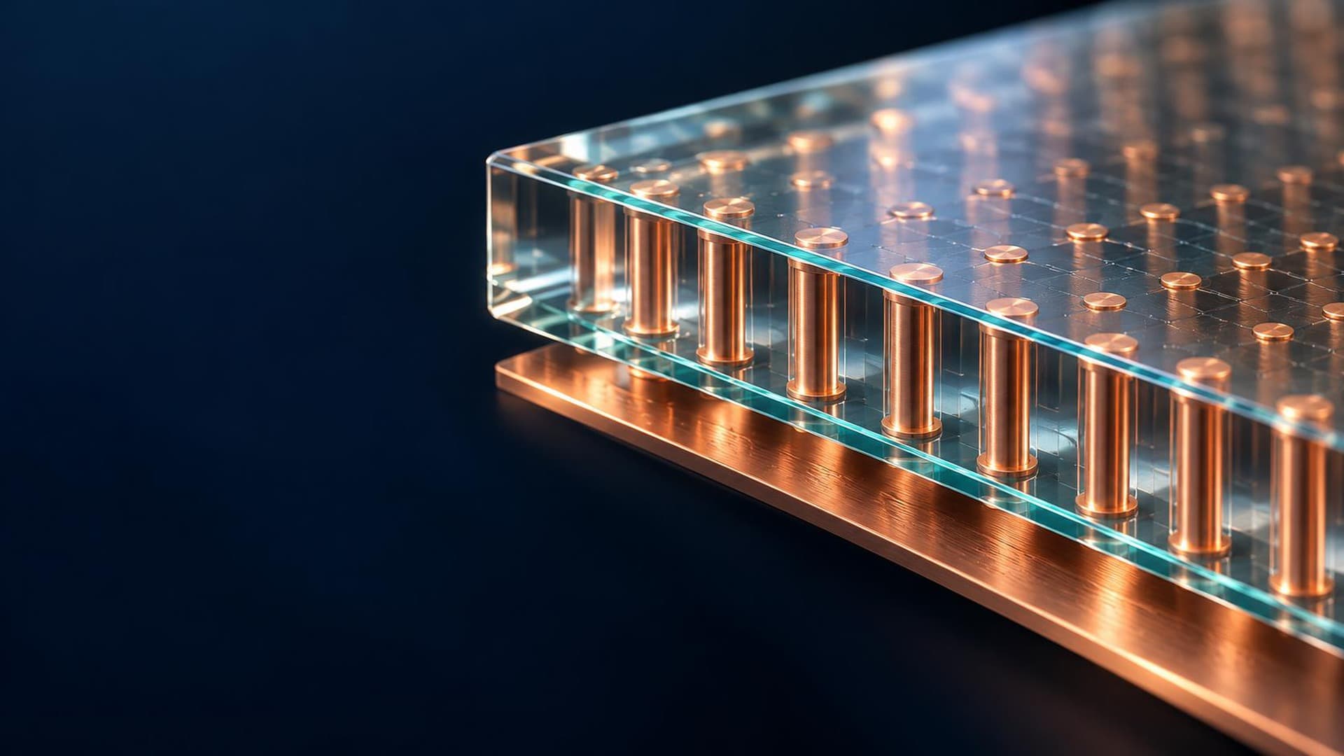
In copper-filled TGVs with double-sided wiring, connections and interfaces are the first to fail under repeated thermal fatigue and short high-temperature loads. The test coupon is a daisy chain that links vias alternately top and bottom through double-sided Cu wiring. Bottom and top connections are staggered so current passes through every via in turn, resistance is measured by the four-wire method with separate current and sense terminals, and via count, shape and wiring thickness are recorded together. IST (Interconnect Stress Test, IPC-TM-650 2.6.26A Method A) passes DC current through the coupon's Cu circuit to heat it by Joule heating, cuts the current at the target temperature and fan-cools it, and repeats the cycle. Heating current is set from room-temperature resistance and the temperature coefficient, and degradation is judged by the change ΔR/R₁ = (Rₙ − R₁)/R₁ × 100 between the first-cycle resistance R₁ and the n-th cycle resistance Rₙ at the same test temperature. The general PCB reference condition is 150 °C, up to 250 cycles, a 10% resistance increase and six coupons; the cycle reaching the threshold is recorded, and thermal imaging, cross-sections and SEM locate the failure. Temperature, cycle count and pass criteria for TGVs are set separately to match the structure and customer conditions. Solder float (IPC-TM-650 2.6.8E) places a dried, fluxed coupon on a 288 ± 5 °C solder surface for 10–11 seconds and cools it to room temperature. Because 288 °C is the bath temperature, the coupon's actual temperature history is checked separately. After floating, cracks at via-to-wiring corners, glass cracking and wall interface delamination are judged from before-and-after resistance and cross-sections. Assembly thermal history is assessed separately by reflow (IPC 2.6.27A, 260 ± 5 °C, at least six passes, cooling below 30 °C between passes), repeated temperature change by chamber thermal cycling (Corning TGV literature condition: −40 to 125 °C, 1,000 cycles, 15 minutes at each extreme), and moisture and electric-field effects by temperature-humidity-bias testing (HAST reference 130 °C, 85% RH, 96 h; THB alternative 85 °C, 85% RH). Failure analysis records electrical connection (four-wire resistance and continuity), copper, glass and interfaces (optical and SEM after sectioning and polishing) and fill condition (X-ray and cross-section) together. Cools proposes an evaluation that compares a conventional interface and a PDA interface of the same geometry in separate IST and solder float coupon groups, contrasting resistance life and cross-sectional damage. This comparison is a proposal, not a measured result.
References
- 1. IPC-TM-650 2.6.26A Interconnect Stress Test
- 2. IPC-TM-650 2.6.8E Thermal Stress, Plated-Through Holes (Solder Float)
- 3. IPC-TM-650 2.6.27A Thermal Stress, Convection Reflow Assembly Simulation
- 4. Corning, TGV reliability literature (2016)
- 5. Zhao et al., 2022 (CC BY 4.0)
Topics
- Glass substrates
- Packaging