About this document
This Technical Note addresses the warpage and component tilt that arise when copper posts and MLCCs mounted together on a wafer are reflowed in one laser step. It describes a process that uses a light-transmitting upper head to support the parts and remove heat.
Download
An English edition is not available yet. The Korean document is below.
Summary
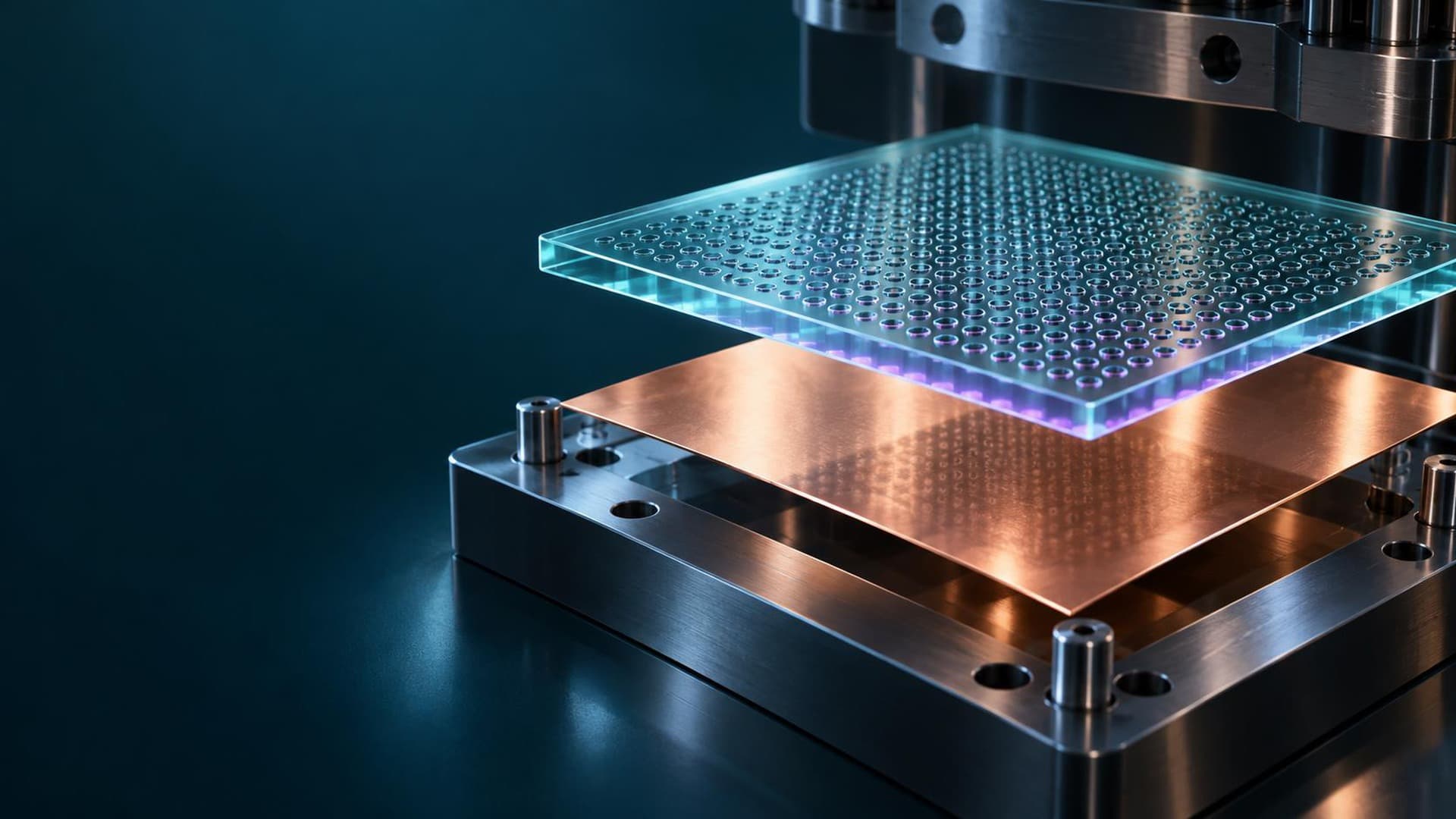
When a wafer-level package is laser-reflowed, heat concentrates on the bonding side and creates a through-thickness temperature difference, and posts tilt or shift in height while the solder is molten. A sapphire or transparent alumina head passes the laser light while touching the parts to hold their posture and recover heat from above. The note covers heating, solidification and cooling with that contact maintained.
Conclusion
In large-area wafer-level packaging (WLP), copper posts and MLCCs are mounted together on the wafer and reflowed in one laser step. The example in the document is an 8-inch wafer carrying 440 units and 17,600 posts (specification from the source data: 450 × 450 × 900 μm Cu posts, 40 per unit). Rapid laser heating concentrates heat on the bonding side and creates a top-to-bottom temperature difference on top of the thermal-expansion mismatch between materials. While the solder is molten, posts tilt or shift in height, so warpage and coplanarity control decide joint quality. The Cools light-transmitting Thermal Clutch uses contact from an upper head for two purposes. The head is made of sapphire or transparent alumina to keep the laser path open, and it supports the parts it touches while drawing heat out through the same contact points. The existing lower chuck stays in place and only the upper head is added; the head's heat storage and spreading are used, and an outer heat-dissipation section is added depending on repeated-operation conditions. The head does not need to touch every part. A common head supports the parts it reaches and tolerates gaps over lower parts caused by height variation. A shared load limit and a lower stop keep a minimum residual solder thickness under the contacted parts. The process has three steps, low-load contact, laser reflow and cooling with contact maintained: the same contacts hold the parts during optical heating and recover heat after irradiation, reducing the through-thickness temperature difference, and the head is released once solidification and cooling are complete. Solder printing, mounting and inspection stay as they are and only an upper head is added at the reflow station, so the process change is confined to the bonding step. The contact face is designed to each product's component layout on a per-unit basis. The document presents the benefits as design effects: improved warpage and post coplanarity and less alignment and bonding failure, with extension from wafers to strips and packages such as FCCSP and FCBGA.
Topics
- Thermal control
- Packaging