About this document
Even after AI racks move to high-voltage DC distribution, a low-voltage, high-current conversion stage remains just ahead of the GPU. This Technical Note looks at moving that stage closer to the load as a cooling-structure problem. The full report is available in Korean. An English summary is provided on this page.
Download
An English edition is not available yet. The Korean document is below.
Summary
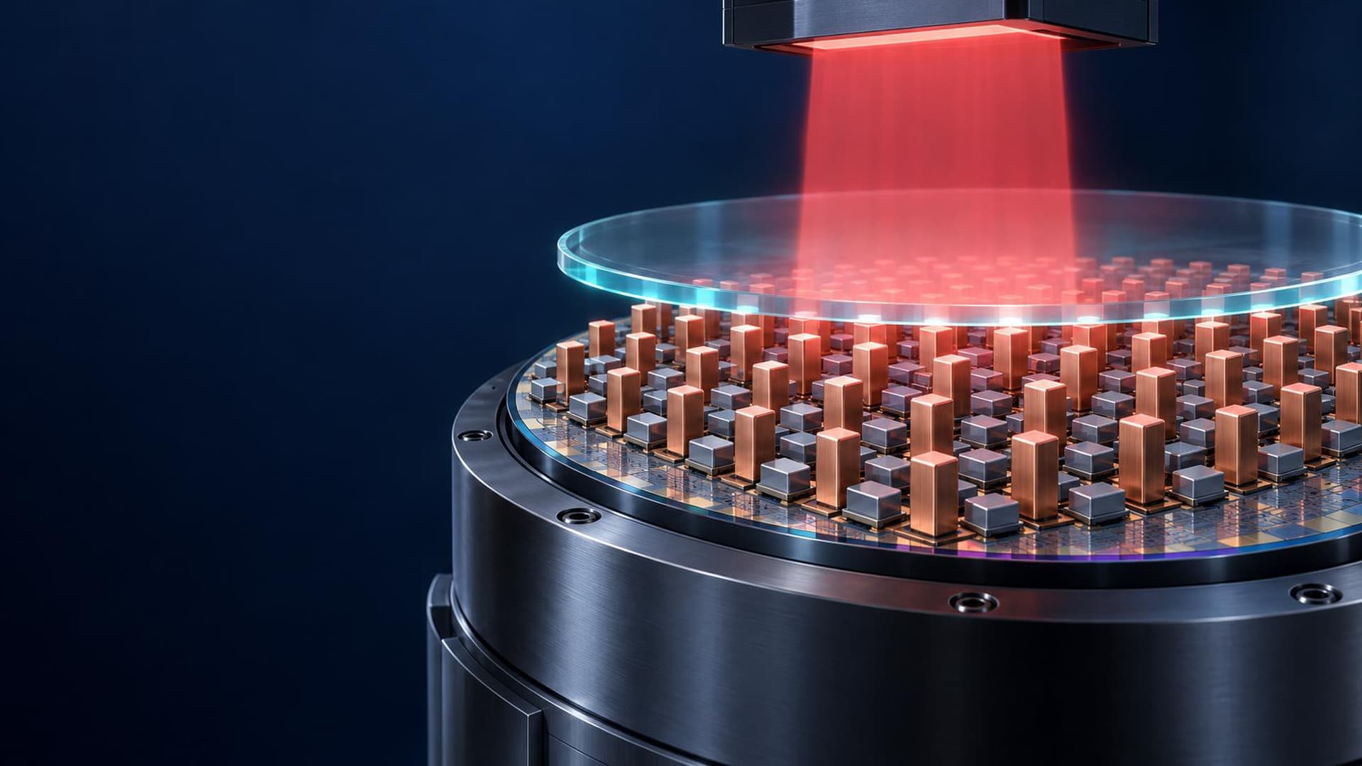
Moving AI rack distribution to 800 VDC does not remove the stage that converts high voltage into low-voltage, high current just before the GPU. What keeps that stage from moving toward the load is heat. A single-side-cooled package has one heat exit, and its thermal interface material (TIM) accounts for a large share of thermal resistance. The note covers a double-sided structure that uses both reaction-bonded silicon carbide (RBSC) electrode faces as direct cooling surfaces, and the thickness needed to fit it into a cold-plate slot.
Conclusion
AI performance is coming to depend less on the speed of a single GPU than on how many GPUs can be tied into one low-latency scale-up domain. What has limited that density is the volume of power equipment. With a 54 V architecture, power shelves take up compute space, which is why rack distribution is moving to 800 VDC. But 800 V does not reach the GPU directly, and the stage that converts high voltage into low-voltage, high current remains. Delivering 600 kW at 48 V means 12,500 A (simple arithmetic), so raising the distribution voltage further does not solve this segment. The question then becomes how close the conversion stage can sit to the load, and the answer is set by cooling, not by electrical design. In a single-side-cooled package, with a substrate on one face and mold compound on the other, heat leaves only through the bottom. The TIM at the end of that series path accounts for up to about 60% of total thermal resistance, according to published industry data. In the Cools structure, the upper and lower RBSC members serve as both electrodes and direct cooling surfaces. With no interposer and no additional bonded interfaces, the TIM layer disappears and the remaining heat path splits into two parallel paths, top and bottom. In a representative design model, removing the TIM brings thermal resistance below half, and the parallel double-sided paths halve it again, for roughly five times the heat-dissipation performance. These are design-model values, not measurements. The practical constraint is thickness and face configuration rather than device performance. Against an example cold-plate slot of 4 mm, a representative commercial module with its heat sink measures 17 mm or more, while the Cools concept design targets 3.2 mm. These are design examples, not industry standards or confirmed measurements. If that thickness holds, part of the centralized low-voltage conversion and distribution function can move into the compute tray and its cooling loop, shortening low-voltage, high-current wiring from rack scale to tray and package scale. The expected side benefit is faster power response to sudden AI load changes, which remains a projected effect that has not yet been measured. The same logic holds along the time axis. Data centers concentrate power in space, pulsed systems concentrate it in time, and the ceiling of a high-energy system is set by repeatability rather than peak output. The first target product is an RBSC double-sided direct-cooled SiC power tile for 800 V AI racks, scaled tile by tile on a shared cooling loop. Its dimensions are conceptual design values.
Topics
- Power semiconductors
- Thermal control